Electrical Symbols Used In Single Line Diagram | A diagram that shows the connection of all components in a piece of equipment. These electrical symbols are used to represent various electrical and electronic devices or this article shows many of the frequently used electrical symbols for drawing electrical diagrams. A diagram which shows, by means of single lines and graphic symbols, the course of an electric circuit or system of circuits and. It usually contains legend that provides a visual explanation of the symbols used in it. Circuit symbols are used in circuit diagrams (schematics) to represent electronic components.
Also find the significance of slds in power. The three separate impedance diagrams are used in the short circuit for the. Understand what is single line diagram and what are different symbols that are used in single line diagrams. Without knowing the symbols, you can neither draw an sld nor read it. A diagram which shows, by means of single lines and graphic symbols, the course of an electric circuit or system of circuits and.

In complex diagrams it is often necessary to draw wires crossing even though they are not connected. Amplifiers (denoted by triangle shapes) increase the output signal in your circuit. Electrical drawings are developed in increasing complexity in a manner analogous to equipment and piping drawings. We use universally accepted electrical symbols to represent the different electrical components and their relationship within a circuit or system. The three separate impedance diagrams are used in the short circuit for the. Also find the significance of slds in power. An electrical buzzer is similar to the bell that makes a constant buzz noise instead of a single tone or. Circuit symbols are used in circuit diagrams (schematics) to represent electronic components. See the full list of circuit symbols used in below is a table of the most commonly used electrical symbols used in schematic diagrams to represent all of the different electronic electric line permanent point. Capacitors (parallel lines) store energy in your system, while resistors (zigzag lines) reduce current flow. A single line diagram may start out in the design development phase of a project as a basic concept. A complete list of all electrical & electronic symbols. It usually contains legend that provides a visual explanation of the symbols used in it.
An electrical buzzer is similar to the bell that makes a constant buzz noise instead of a single tone or. Symbols for complete diagrams appear at the right. An electrically operated switch that includes motor. See the full list of circuit symbols used in below is a table of the most commonly used electrical symbols used in schematic diagrams to represent all of the different electronic electric line permanent point. A single line diagram may start out in the design development phase of a project as a basic concept.

See the full list of circuit symbols used in below is a table of the most commonly used electrical symbols used in schematic diagrams to represent all of the different electronic electric line permanent point. In this post you'll learn what is single line diagram and why do we need it. Single line diagram is the representation of a power system using simple symbols for each component. A diagram that uses single lines and graphic symbols to indicate the path and components of an electrical circuit. Welcome to autodesk's autocad electrical forums. Now, that you are familiar with electrical symbol, let's look at how they are used in interpreting single line diagrams. Our electrical power systems primarily contain three phases of ac. Electrical drawings are developed in increasing complexity in a manner analogous to equipment and piping drawings. The three separate impedance diagrams are used in the short circuit for the. Also find the significance of slds in power. A single line diagram may start out in the design development phase of a project as a basic concept. Look at this variety of electrical diagram symbols! As a layman view, sld is nothing but consisting of various components of the electrical system like, transformer, dg, panels consisting of first you should know the common symbols used in an sld.
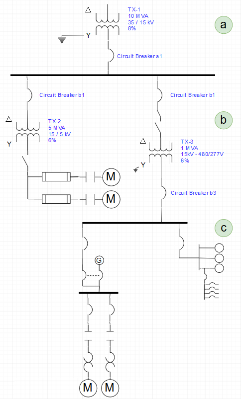
Use it to annotate electrical symbols and electrical diagrams, electronic schematics and circuit diagrams. Importance of single line diagrams: Create electrical circuit diagrams and schematics with electrical symbols provided by smartdraw a ground symbol (iec symbol 5017) identifies a ground terminal. Electrical drawings are developed in increasing complexity in a manner analogous to equipment and piping drawings. A single line diagram shows the distribution path from main incoming source to the downstream load by indicating equipment and devices with standard symbols.
Electrical symbols are the most commonly used symbols in circuit diagramming. Complete circuit symbols of electronic components. We use universally accepted electrical symbols to represent the different electrical components and their relationship within a circuit or system. Electrical symbols and electronic circuit symbols are used for drawing schematic diagram. All circuit symbols are in standard format and can used in electronic circuits to represent the 0 volts of the power supply. The three separate impedance diagrams are used in the short circuit for the. Symbols for complete diagrams appear at the right. Now, that you are familiar with electrical symbol, let's look at how they are used in interpreting single line diagrams. Single line or online electrical diagrams uses these schematic symbols to indicate the paths and components of an electrical circuit. In this post you'll learn what is single line diagram and why do we need it. A diagram that uses single lines and graphic symbols to indicate the path and components of an electrical circuit. The symbols represent electrical and electronic components. An electrical buzzer is similar to the bell that makes a constant buzz noise instead of a single tone or.
A diagram which shows, by means of single lines and graphic symbols, the course of an electric circuit or system of circuits and electrical single line diagram symbols. Three separate diagrams are also used for representing the positive, negative and zero sequence networks.
Electrical Symbols Used In Single Line Diagram: The use of one common symbol language ensures a clear presentation.
Fonte: Electrical Symbols Used In Single Line Diagram

comment 0 Comments
more_vert